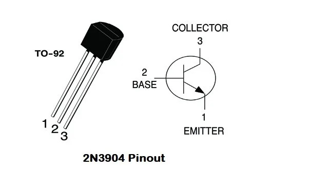
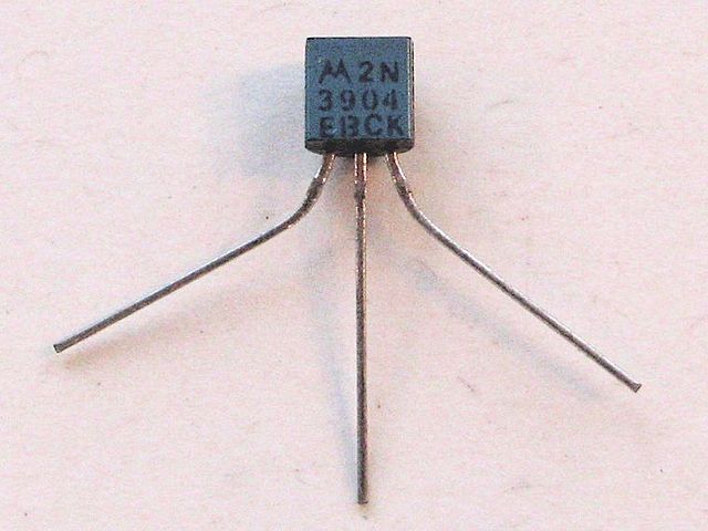
The 2N3904 is a popular NPN bipolar junction transistor (BJT) commonly used for general-purpose amplification and switching. Here’s an overview of its application circuit, usage, and selecting the operating point:
Application Circuit:
The 2N3904 can be used in a variety of amplifier and switching circuits. For simple amplification purposes, a common-emitter configuration is often used. Here's a basic example of how a 2N3904 can be connected in a common-emitter amplifier circuit:
In this circuit, R1 forms the input resistor, while R2 forms the collector load resistor. The output is taken from the collector. Decoupling capacitors for AC coupling and power supply bypassing might be added depending on the application.
Usage:
The 2N3904 is commonly used in various applications:
-
Amplification:
- It is often used in small signal amplification circuits due to its high current gain and low noise characteristics.
-
Switching:
- The 2N3904 can be used as a switch to control larger currents and voltages using a small base current.
-
Oscillators:
- It can be utilized in producing oscillations in simple oscillator circuits.
-
Digital Logic:
- In older digital logic families, it was occasionally used as a basic switching element.
Operating Point Selection:
Selecting the operating point involves setting the collector current (IC), collector-emitter voltage (VCE), and base current (IB) to the appropriate values for the specific application, ensuring the transistor operates within its safe operating area:
-
Biasing:
- The biasing of the transistor, typically through a base resistor, determines the operating point. A stable bias point is chosen to ensure proper amplifier operation.
-
Quiescent Point:
- In amplifier circuits, the quiescent point, or Q-point, is often chosen to be at the middle of the DC load line to allow for maximum symmetrical signal swing.
-
Collector Current (IC):
- IC is chosen based on the required gain and collector power dissipation, ensuring it remains within the transistor's rated limits (often noted on the datasheet).
-
Collector-Emitter Voltage (VCE):
- VCE should be within the rated breakdown voltage and in the linear region for the specific application. Ensure it avoids saturation or cutoff when amplifying signals.
Selecting the appropriate operating point requires a consideration of the specific requirements of the circuit, such as the desired gain, the type of signal being amplified or switched, and the power dissipation limits of the transistor.
Always refer to the 2N3904 datasheet and relevant application notes to ensure correct usage and operating point selection based on your specific circuit requirements.